What is a Changeover Relay Switch?
This post highlights the Changeover switch relays covered in the range of auto electrical products at Arc Components Limited. The relays supplied in-store are configured to DIN 72552 terminal standardisation. Examples can be found in the "Switch Relay" section.
What is a Changeover relay?
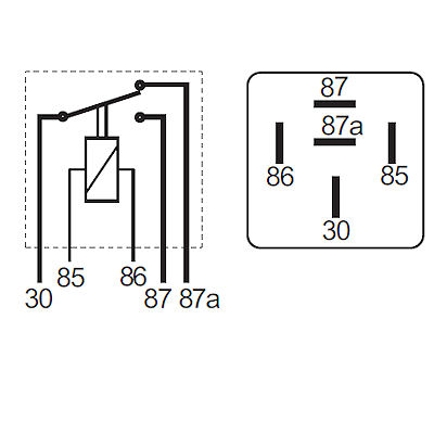
The most common changeover function relays are produced to switch a single feed line (usually Positive - position 30) between two active functions in a circuit. The relay is switched manually via a toggle/push switch or remotely through the circuit. A simple 'single line Changeover switch' is achieved by switching a single line input from terminal position 30, at rest in the normally closed terminal position 87a (indicated by the 'Thick Set' black lines on the diagrams below), to the number 87 position. When the coil is energised, the line switches from terminal 87a to terminal 87, remaining in the second function until the power to the energised coil (via 85 and 86, which can be swapped in some applications) is switched off, returning the circuit to the normally closed (NC - 87a) position. A typical explanation of this function is associating it with a headlight "dipped beam", where momentary switching to full beam and then back to the dipped position (with both output positions 'by design' being active). In practice, it would be correct to say that changeover relays have been used (sometimes by vehicle manufacturers) to achieve a Normally Open or Normally Closed Make and Break action by leaving a line-out position undesignated.
Many configurations of a changeover relay are used for automotive electrical circuit switching, each allowing a variation on the switch operation; versions include Normally Closed (NC or active circuit), latching and coil suppression. One of these, the latching relay, allows a mechanical (or in some cases an electronic) function that retains the switched position even when power to the coil is cut; helpful in conserving power, the line switch is reactivated (usually with a momentary push switch) only when the coil is energised again. Typical builds are:
- Standard line Changeover relay: (as described above), switching input 30 between 87a (NC) and 87.
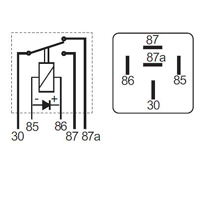
- Changeover relays with diode: used for suppressing coil voltage spikes, 85 and 86 terminals become polarity sensitive; 86 must remain a positive designation if the diode tracks according to the diagram example below.
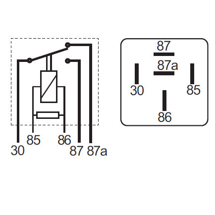
- Changeover relays with a resistor: used for a more reliable suppressing of coil voltage spikes, 85 and 86 can be swapped for coil energising in some instances as the terminals do not become polarity sensitive.
- Mechanical latching relay: allowing switching circuits, and the position remains 'made' until the coil is energised again.
Relay Coil - Positive and Negative Coil Energising by DIN 72552 Definition.
| Terminal or Contact | Identification |
|---|---|
| 85 | Relay coil - Negative. |
| 86 | Relay coil - Positive. |
Relay Contacts - Line Feed or Switching by DIN 72552 Definition.
| Terminal or Contact | Identification |
|---|---|
| 87 | Common contact. |
| 87a | Normally Closed contact. |
| 87b | Normally Open contact. |
| 88 | Common contact 2. |
| 88a | Normally Closed contact 2. |
| 88b | Normally Open contact 2. |
| 30 | Feed or line in - Positive. |
Examples of Changeover Relays:
| Standard Changeover ( 87a, NC) | Changeover Relay with Diode | Changeover Relay with Resistor |
|---|---|---|
 |  |  |
| Mechanical Latching Relay | ||
 |
Start browsing for your Auto Electrical parts: Here.