| 
Need help? Email us: sales1@arc-components.com

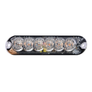
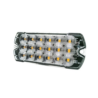
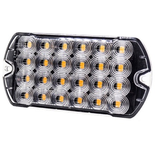
0-441-81 Durite 6 LED Amber Warning Light With 11 Flash Patterns

0-441-81 Durite 6 LED Amber Warning Light With 11 Flash Patterns
£19.89 Excl. VAT
RRP £22.60 Excl. VAT
Initial Savings
£2.71
(£23.87 Inc. VAT)
Earn 19 Loyalty Points
   
Available
Model
0-441-81
Bar Code
5056119165401
Part Number
0-441-81
Brand
Durite
Colour
Amber
Voltage
10V to 30V DC
Material
Polycarbonate/Aluminium/Copper
Weight
85 g
 

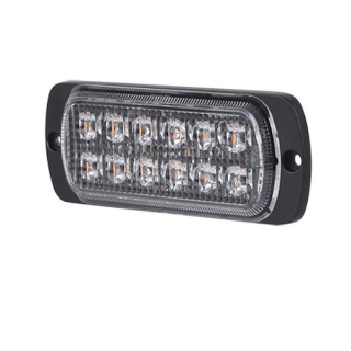
 Durite 6 LED Amber Warning Light with a choice of 11 selectable flash patterns

  • Voltage 12V-24Vdc (10-30Vdc)
  • 6 x 1W LEDs.
  • 11 flash patterns.
  • Protected to IP67/69K.
  • Polycarbonate lens and aluminium base.
  • ECE R65, R10 EMC, RoHS, CE, and UKCA approved.

Dimensions

  • Length: 82.7mm
  • Width: 35.7mm
  • Height: 15.5mm

Wiring

  • Red: 10-30Vdc
  • Yellow: SYNC
  • White: ASYNC
  • Black: Ground (-VE)

Flash Patterns

Sequence Description FPM
1 Single (all) 150
2 Quad (alternate) 75
3 Quint (all) 60
4 Triple (alternate) 100
5 Flicker 1200
6 Double (alternate) 75
7 Triple 100
8 Single (all) 62
9 Single (all) 107
10 Combo 112
11 Steady of 30% brightness N/A

Specifications

Type LED Slim Amber Warning Lamp
Voltage 10-30Vdc
LEDs 6 x 1W LEDs
Wattage 6W
Current draw 0.48A at 12Vdc, 0.25A at 24Vdc
Flash Patterns 11
Material Construction PC Lens, aluminium base
IP Rating IP67 / IP69K
Operating Temperature -45°C - +60°C
Weight 0.077Kg
Certificates ECE R65 (Class 1), R10 EMC, RoHS, CE and UKCA.

General Warnings and Instructions

 Before using this unit, please read these instructions carefully. Take special care to follow the warnings and safety suggestions listed below. Keep these instructions for future reference. There are no user-serviceable parts within the unit; refer servicing to qualified service personnel.

Precautions

  1. Proper installation of this product requires the installer to understand automotive electronics, systems and procedures well.
  2. If mounting this product requires drilling holes, the installer MUST be sure that the drilling process could damage no vehicle components or other vital parts. Check both sides of the mounting surface before drilling begins. Also, de-burr the holes and remove any metal shards or remnants.
  3. Do not install this product or route any wires in the deployment area of your airbag. Equipment mounted or located in the airbag deployment area will damage or reduce the effectiveness of the airbag or become a projectile that could cause serious personal injury or death. Refer to your vehicle owner’s manual for the airbag deployment area. The User/Installer assumes full responsibility for determining the proper mounting location based on providing ultimate safety to all passengers inside the vehicle.
  4. Do not attempt to activate or control this device in a hazardous driving situation.
  5. This product contains either strobe light(s), halogen light(s), high-intensity LEDs or a combination of these lights. Do not stare directly into these lights. Momentary blindness and/or eye damage could result.
  6. Use only soap and water to clean the outer lens. The use of other chemicals could result in premature lens cracking (crazing) and discolouration. Lenses in this condition have significantly reduced effectiveness. Inspect and operate this product regularly to confirm its proper operation and mounting condition.
  7. It is recommended that these instructions be stored in a safe place and referred to when performing maintenance and/or reinstallation of this product.
  8. A good electrical connection to the chassis ground must be made for this product to operate at optimum efficiency. The recommended procedure requires the product ground wire to be connected directly to the NEGATIVE (-) battery post.

Mounting

  1. Place the unit against the mounting surface.
  2. Mark the areas where the mounting holes are to be drilled. Confirm that the drilling process could damage no vehicle parts.
  3. Using a bit size for a no. 304 metal screw, drill two mounting holes, a 0.5” diameter. Wire passage hole(s) must also be drilled. Thoroughly de-burr all hole(s).
  4. Pass the wires through the hole(s) in the gasket and through the wire passage hole(s) in the mounting surface. Fix the light head to the mounting surface.

General Setup Instructions

  • To set the flash pattern: Touch the yellow cable to a live connection 10-30V for one second. Repeat the process until the desired flash pattern is selected.
  • To synchronise: Connecting all units with black, red and yellow wires will synchronize all light heads.
  • Touching red wires to the yellow wires for about 5 seconds will change the flash pattern (all units must be reset individually on the first same pattern to remain synced together on the same pattern).
  • To set the alternate flash mode: Connecting all units with Black, Red and Yellow wires will synchronize all light heads.
    Touching the Red wires to the Yellow wires for about 5 seconds will change the flash pattern (all heads must be reset individually on the same pattern first to remain synced together on the same patterns).
  • Connecting white wires to the red wire will set an alternating flash.
  • Do not connect the Yellow wire to the Red wire, so all units remain synced together on the same flash patterns.


Delivery
 
UK Mainland Postage Offer

Delivery Options Our Free UK Mainland Postage and Packaging Service offers unbeatable value for money. The free UK Standard shipping is automatically applied to your shopping cart page with no additional cost when you reach the £50.00 minimum order value.

 We use Royal Mail Standard or Recorded Delivery for light, low-value orders and we use FedEx, UPS, Parcel Force, and other major courier services for larger and more valuable consignments.

 
International Consignments

 Our international customers will need to provide the exact Card Holder Address (Invoicee) as the first address for payment processing. Please note that PO Box addresses are not acceptable as delivery addresses by some couriers. All export orders must be placed and paid for online. Proforma Bank Transfer IBAN and SWIFT payment methods are available to create online.

Also Bought

Customer Feedback (0)
Leave a Review