Related Products
 .jpg) |
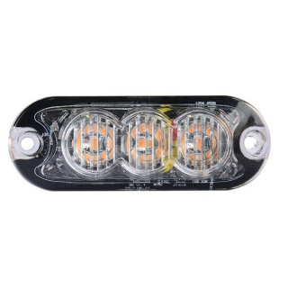
Durite Amber R65 high intensity warning light provides higher visibility of your vehicle, improving road safety during the day or night.
£37.54
Excl VAT
AvailableExcl VAT
 .jpg) |
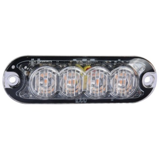
Durite Amber R65 high intensity warning light provides higher visibility of your vehicle, improving road safety during the day or night.
£38.67
Excl VAT
AvailableExcl VAT
 .jpg) |
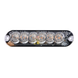
Durite Amber R65 high intensity warning light provides higher visibility of your vehicle, improving road safety during the day or night.
£42.15
Excl VAT
AvailableExcl VAT
 .jpg) |
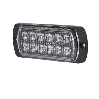
0-441-74 R10 high intensity 2 x 6 Amber LED warning light (19 flash patterns).
£33.76
Excl VAT
AvailableExcl VAT
 .jpg) |
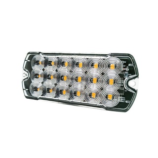
Durite 12/24V R10 R65 high intensity 18 Amber LED warning light with 19 flash patterns.
£42.98
Excl VAT
AvailableExcl VAT
 .jpg) |
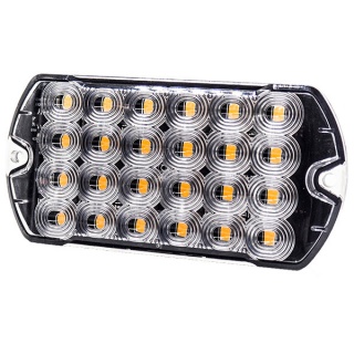
Durite 12/24V R10 R65 high intensity 24 Amber LED warning light with 19 flash patterns.
£46.94
Excl VAT
AvailableExcl VAT
Leave a Review