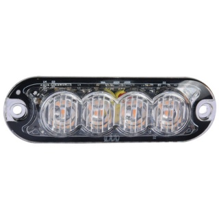
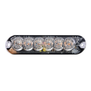
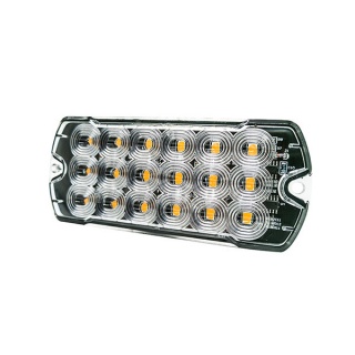
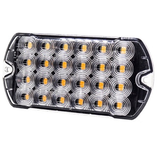
Durite super slim amber LED warning light with 7 flash patterns.
- 6 x 3W LEDs
- 7 flash patterns
- Protected to IP69K
- ECE R65 (Class 2) R10 EMC, RoHS CE UKCA, and CAP 168 ICAO approved
Dimensions
- Length: 118mm
- Width: 13mm
- Height: 13mm
About the Slim Amber LED Warning Light
Durite super slim Amber LED warning light is an extremely versatile warning device. It is available in single and tricolour options to meet the needs of all applications, from amber safety and commercial vehicles to emergency services and covert vehicles. The lamp features a strong polycarbonate lens on an aluminium body to maximise protection from debris impact and absorb heat dispersion. This product also boasts major industry requirements such as IP69K for the toughest environments, EMC R10, ECE and R65 approvals and comes as standard with 7 flash patterns, including ICAO/CAP168 airport pattern. It includes an industry-first TD-Sync feature allowing users to synchronise and direct traffic with this inbuilt capability.
7 Flash Patterns Total
1. Quad 2. Triple 3. Double 4. Single 5. Quad/single 6. Quad/triple/double/single 7. CAP168
Mounting
- Place the unit against the mounting surface.
- Mark the areas where the mounting holes are to be drilled. Confirm that no vehicle parts could be damaged by the drilling process.
- Using a bit size for a no. 304 metal screw, drill two mounting holes, a 0.5-inch diameter. Wire passage hole(s) must also be drilled. Thoroughly de-burr all hole(s).
- Pass the wires through the hole(s) in the gasket and through the wire passage hole(s) in the mounting surface. Fix the light head to the mounting surface.
Wiring Colours
- Yellow: Synchronisation
- Brown: Pattern select
- Orange: Power (V2) 11-30V dc
- Green: Config
- Red: Power (V1) 11-30V dc
- Black: 0V ground
- Blue: DIM
Specifications
| Type | LED slim Amber warning lamp |
| Voltage | 11-32V dc |
| LEDs | 6 x 3W LEDs |
| Flash patterns | 7 |
| Material Construction | Polycarbonate |
| Operating temperature | -40 to +105 degree centigrade |
| Protection | IP69K |
| Weight | 38G |
| Certificates | ECE R65 (Class 2), R10 EMC, RoHS, CE, UKCA, CAP 168 ICAO |
Warnings
Before using this unit, please read these instructions carefully. Take special care to follow the warnings and safety suggestions listed below. Keep these instructions for future reference.
Safety Warnings For Translation
- Proper installation of this product requires the installer to understand automotive electronics, systems and procedures well.
- If mounting this product requires drilling holes, the installer MUST be sure that no vehicle components or other vital parts could be damaged by the drilling process. Check both sides of the mounting surface before drilling begins. Also, de-burr the holes and remove any metal shards or remnants.
- Do not install this product or route any wires in the deployment area of your airbag. Equipment mounted or located in the airbag deployment area will damage or reduce the effectiveness of the airbag or become a projectile that could cause serious personal injury or death. Refer to your vehicle owners manual for the airbag deployment area. The User/Installer assumes full responsibility for determining the proper mounting location based on providing ultimate safety to all passengers inside the vehicle.
- Do not attempt to activate or control this device in a hazardous driving situation.
- This product contains high-intensity LEDs. Do not stare directly into these lights. Momentary blindness and/or eye damage could result.
- Use only soap and water to clean the outer lens. The use of other chemicals could result in premature lens cracking (crazing) and discolouration. Lenses in this condition have significantly reduced effectiveness. Inspect and operate this product regularly to confirm its proper operation and mounting condition. Do not use a pressure washer to clean this product.
- It is recommended that these instructions be stored in a safe place and referred to when performing maintenance and/or reinstallation of this product.
- A good electrical connection to the chassis ground must be made for this product to operate at optimum efficiency. The recommended procedure requires the product ground wire to be connected directly to the NEGATIVE (-) battery post.
.jpg)
.jpg)
.jpg)
.jpg)
.jpg)
.jpg)